STUDY OF THE ELECTRICAL LOADING OF SEMICONDUCTOR SWITCHING ELEMENTS IN A STEP VOLTAGE REGULATOR
BARUDOV Emil, BARUDOV Stefan and PANOV, Emil
Technical University – Varna, 9010, No.1 Studentska str.
E-mail: ugl@abv.bg
Abstract : The voltage of the separate consumers in limited power networks can be maintained within the allowed boundaries by automated step changeover of an autotransformer. The transient phenomenon of a thyristor switch breakeover at the boost winding of the autotransformer is studied.
Keywords: step changeover, autotransformer, regulator, model, transient process.
Introduction: There are electrical networks where the phase voltage varies far above the allowable limits depending on the operational modes of some of the ultimate consumers. This forces application of individual regulation of the phase voltage directly at the very consumers. The regulation can be effected by stepwise automated changeover of the autotransformer terminals. The general principles related to the solution of similar problems are discussed in [1...5].
The operation of the stepwise voltage regulator is determined by the length of the transient process of the individual semiconductor switches and by the electrical load in transient mode. The length of the transient process is analysed in [6].
The present task is to study, at the same conditions, the electrical loading of the semiconductor switches in transient mode of operation.
|
|
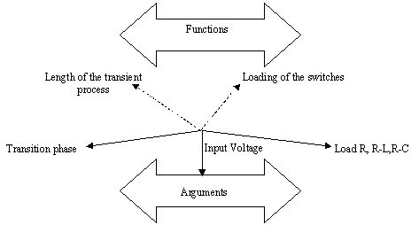
| Fig. 1 Arguments and functions diagram of the study. |
The examination is equivalent to a study in multidimensional space, where three of the considered variables are: regulator input voltage, initial phase of switchings and load current, while the lentgth of the transient process and the regulator current amplitudes are functions.
Figure 1 shows graphically the axes of this multidimensional space and thus the complexity of the study.
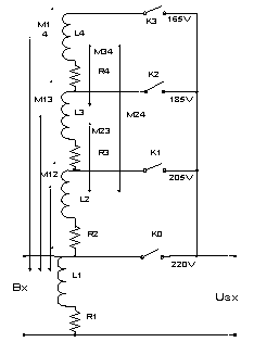
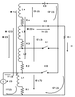
Figure 2 presents the model of voltage regulator with parameters ecountered in the computer sumulations. Fig 3 shows the equivalent circuit of the transient process The switching elements are idealized, i.e. their ohmic resistances are assumed to be equal to zero.
On the basis of the developed program AVTO1 under MATLAB,
we receive the values of the currents at the respective change of the switching
phase, as well as the character of the load. Examinations are made for currents
I2max ![]() Itmax, I3max
è I4max - switching currents of Ê2 and
Ê3 switches.
Itmax, I3max
è I4max - switching currents of Ê2 and
Ê3 switches.
The computer simulations display the following regularities:
Regarding the load current I2max:
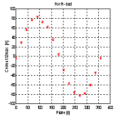
In case of active load, I2max is largest at φ=90°; 270° and is minimal for φ=0°; 180°; 360°.
Sinusoidal distribution of the I2max - phase relationship is observed (Figure 4).
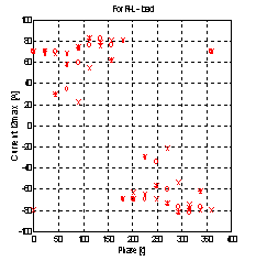
At active-inductive load I2max does not depend on the phase in 0°-180° and 180°-360° intervals (Figure 5).
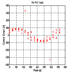
In case of active-capacitive load I2max has sinusoidal distribution. Overcurrents are observed at φ=112,5° and 292,5° (Figure 6).
|
|
|
| Fig.2 Equivalent circuit of the step voltage regulator |
Fig. 3 Equivalent circuit of the transient process. |
The following is observed for the switching current I3max :
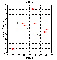
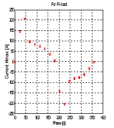
With active load, I3max has maximal values at φ=45°; 225°, and minimal at φ=0°; 180°; 360°. Overcurrents are observed at φ=45°; 225° (Figure 7).
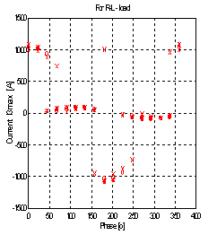
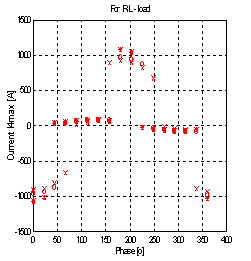
At active-inductive load, I3max is largest in [0°; 45°] and [180°; 225°] intervals. Overcurrents are observed in these itervals, while for the rest of them I3max has minimal values (Figure 8).
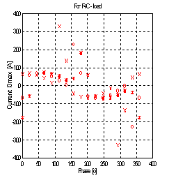
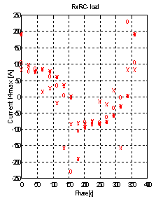
At active – capacitive load, I3max is grouped around sinusoidal distribution. Overcurrents are observed with some spread in the intervals [112,5°; 202,5°] and [292,5°; 22,5°] (Figure 9).
The following is observed for the switching current I4max :
With active load I4max has maximal values at φ=45°; 225°. Overcurrents are present at these phases while the minimal values are at φ=0°; 180°; 360° (Figure 10).
At active-inductive load I4max has maximal values in the intervals [0°; 45°] and [180°; 225°], while the minimal values are located in the rest of the intervals (Figure 11).
At active –capacitive load, I4max is grouped around sinusoidal distribution with some spread in the [67,5°; 180°] and [247,5°; 360°] intervals – overcurrents are present there (Figure 12).
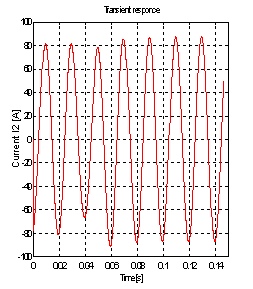
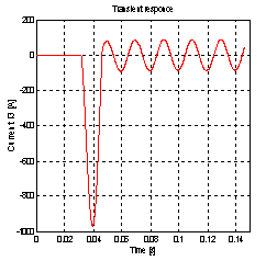
Figures 13 and 14 show in the time domain the reaction of the load current i2(t) and the current i3(t) through the closing Ê3 switch, for ZT=3,3846.e- j 75° and series equivalent load circuit at φ=202,5° initial switching phase. It is evident that the currenti3(t) reaches i3max=-950À during the transient process.
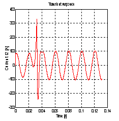
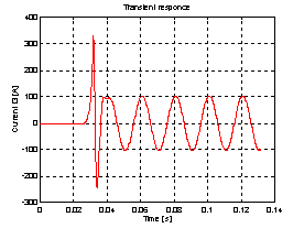
Figures 15 and 16 present the load current i2(t) and the current i3(t) for ZT=3,3846.e- j 75° and series equivalent load circuit, at initial switching phase φ=112,5°. Both currents reach maximal values of 330À.
|
|
|
| Fig 4 Dependence of I2maxcurrent from the switching phases. |
Fig. 5 Dependence of I2maxcurrent from the switching phases. |
|
|
|
| Fig. 6 Dependence of I2maxcurrent from the switching phases |
Fig. 7 Dependence of I3maxcurrent from the switching phases |
|
|
|
| Fig. 8 Dependence of I3maxcurrent from the switching phases |
Fig. 9 Dependence of I3maxcurrent from the switching phases |
|
|
|
| Fig. 10 Dependence of I4maxcurrent from the switching phases |
Fig. 11 Dependence of I4maxcurrent from switching phases |
|
|
|
| Fig. 12 Dependence of I4max current from the switching phases. |
Fig. 13 Time domain response of i2(t) current for R-L load. |
|
|
|
| Fig. 14 Time domain response of i3(t) current for R-L load. |
Fig. 15 Time domain response of i2(t) current for R-C load. |
|
|
|
| Fig. 16 Time domain response of i3(t) current for R-C load. |
|
CONCLUSIONS
The examinations show that emergency states exist for the three types of loads (active, inductive and capacitive), occuring at specific values of the starting phase of switchings – i.e of the transient process. This requires special control identifying the type of the load and tracking the phase of onset of switching. This control should select the switching moments in a way alowing as short as possible transient processes with minimal amplitudes, i.e. to provide “accurate” activation of the switches. This can be achieved under microprocessor control, monitoring the operation of the regulator.
REFERENCES
[1] Minchev Ì., Penchev P. Contactless Aparatuses, Technika 1976 (in Bulgarian)
[2] Porudominskiy V. Switching Devices for Transformers under Load, Energia 1974 (in Russian)
[3] Lipkowskiy Ê. Transformer-Switching Actuator Structures of the Alternating Current Converters, Naukova Dumka 1983 (in Russian)
[4] Barudov St., Dimitrov D, Barudov Em. Functional Performance of Transformers in a Contactless Voltage Stabilizer SIELA 2001 (in Bulgarian)
[5] Barudov Em., Barudov St., Panov Em. Switching Processes in a Step Voltage Regulator, Annual Proceedings 2003, Technical University Varna.
[6] Barudov Em., Barudov St., Panov Em. Study of the Length of the Transient Process in a Step Voltage Regulator.
